
Standard required to be used on all DGLVR stream crossing replacements, unless an Exemption from DGLVR Stream Crossing Standard applies. See section 7.1 of this manual for additional information.
I. DEFINITIONS
Aggradation: Deposition of sediment and corresponding increase in streambed elevation, often due to inability of the stream to adequately convey its sediment load during flood.
Anticipated Scour Depth: Depth of expected scour used to determine structure bury depth based on observed maximum reference reach pool depth and a factor of safety.
Aquatic Organism Passage: Unimpeded movement of aquatic organisms through the road/stream crossing.
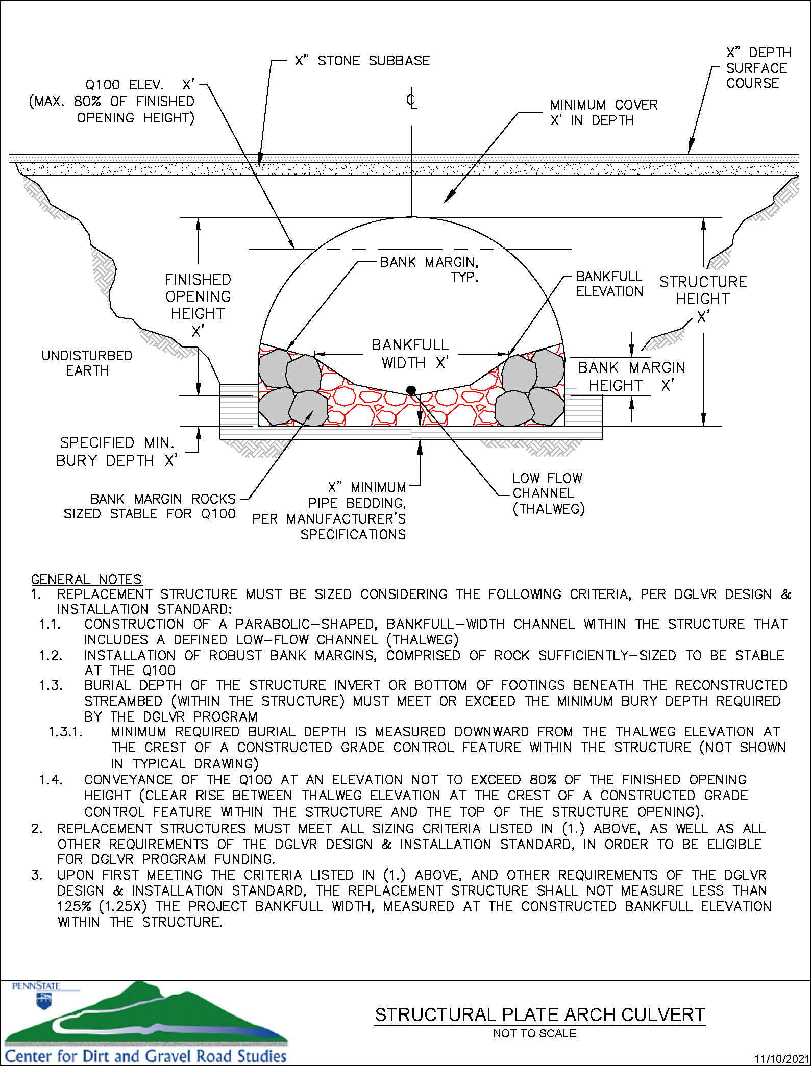
Bankfull Elevation: In non-confined channels, the elevation point at which the stream typically accesses the floodplain. Channel dimensions at the bankfull elevation convey the channel-forming or dominant discharge.
Bankfull Width: A site-specific, field-derived measurement of channel width at the bankfull elevation.
Bank Margins: Large rock placed along the outside edges of the reconstructed bankfull channel within the stream crossing structure. Placement of the bank margins define bankfull channel width and bank margin (bankfull) elevation/height through the structure.
Bedform: Typical sequence of streambed features through the project reference reach (riffles/pools, step/pool, etc.).
Channel Continuity: Relative consistency and connectivity of a stream channel upstream, through, and downstream of a road/stream crossing, in regard to physical characteristics of the channel such as slope, planform, dimensions, profile, and bedforms.
Continuity Slope: Slope of the reconstructed section of streambed necessary to re-establish a relatively continuous slope, profile, and bedforms (channel continuity) along the entire length of stream extending upstream, through, and downstream of the new crossing.
Crossing: Refers to the location of a road/stream crossing structure.
Cross-Section Survey: A survey conducted across the channel (perpendicular to the thalweg) to produce a graphical representation of channel dimensions including shape, depth, and width.
Degradation: Accelerated erosion and transport of sediment from the streambed and banks, and corresponding lowering of the streambed elevation. Often associated with increased scour potential due to channel constriction or abrupt increase in channel slope.
Finished Opening Area: The unobstructed area within the structure after accommodating for stream bed material, low flow channel, and bank margins.
Finished Opening Height: Vertical distance measured from the thalweg elevation at the crest of a constructed grade control feature inside the replacement structure, upward to the top of the culvert opening or bottom of bridge beam.
Flood Resiliency: Reducing the risk of flood damages to people and infrastructure by planning and implementing measures that improve floodwater conveyance and provide for long-term stability of a self-maintaining stream corridor.
Grade Control: Natural or manmade structures that control channel elevation, dictate channel slope, and maintain bedforms. Common types include riffles, cascades, steps, rock clusters, and large wood features.
Intermittent Watercourse: A stream or waterway with surface flow during various times of the year when groundwater inputs are sufficient to provide streamflow. At other times of the year, when there is insufficient groundwater input, the stream channel may be dry.
Invert: Interior bottom elevation of stream crossing structure.
Key Pieces: Largest rocks in the reconstructed streambed substrate. Often these can be clustered to provide areas of minor, frequent grade control along the length of the channel bed in-between more robust constructed grade control features.
Longitudinal Profile Survey: Survey of the stream channel, typically measured from upstream to downstream along the channel thalweg, to capture prominent features such as channel elevations, depths, and slopes at bedform features such as riffles, pools, runs, glides, and step/pools.
Low Flow Channel: Portion of the channel commonly wetted during stream base flow.
Outlet Scour Pool: An overly widened and deepened pool bedform feature often (but not always) located immediately downstream of an undersized crossing.
Perennial Watercourse: A stream or waterway with surface flow throughout the entire calendar year.
Q100: The 100-year recurrence interval of stream flow. In any given year, there is a 1% probability that a flow of that magnitude or greater would occur.
Reconstructed Reach: Section of stream to be constructed upstream, through, and downstream of the new structure to re-establish channel continuity between the tie-in points.
Reference Reach: Section of stream channel that best reflects the “typical” natural, minimally impacted physical characteristics (profile, dimension, planform, and dominant bedform) of the channel. For stream crossing projects, the reference reach is located beyond the extent that the channel impacts are associated with the existing structure. Site Assessment (survey) of the reference reach is used as a blueprint for design of the reconstructed reach.
Site Assessment: Survey of longitudinal profile and cross-sections through, and adjoining to, the project site used to inform project design.
Structure: A road/stream crossing structure, such as a culvert or bridge, constructed across a stream to provide controlled access for vehicles.
Substrate: Mixture of rock that composes the streambed.
Thalweg: The line of lowest elevation along the flowpath of a stream channel. Dimensionally, this is reflected as the lowest point of elevation in the channel cross-section.
Tie-in Points: Locations of existing or constructed grade control features where the upstream and downstream limits of the reconstructed reach transition to the existing stream channel. Tie-in points define the limits of the reconstructed reach necessary to achieve channel continuity upstream, through, and downstream of the crossing.
II. PURPOSE
This standard is applied for the purposes of:
A. Providing greater flood resiliency at road stream crossings and reducing maintenance of undersized crossings.
B. Improving water quality by reducing sediment and erosion occurring at the road and stream interface.
C. Reducing streambed and streambank degradation.
D. Constructing and maintaining stream channel continuity through the road profile.
E. Accommodating aquatic organism passage upstream, downstream, and through the road crossing.
F. Repairing and stabilizing stream channels damaged by undersized stream crossings.
III. CONDITIONS WHERE PRACTICE APPLIES
This practice applies to stream crossing structure replacements and installations on state or local publicly owned roads where:
A. DGLVR funding is used, in whole or in part, to fund a stream crossing replacement.
B. An intermittent or perennial watercourse exists.
C. A defined bed and bank convey water to a roadway.
IV. GENERAL CRITERIA APPLICABLE TO ALL STREAM CROSSING INSTALLATIONS
A. Refer to the Dirt, Gravel, and Low Volume Roads (DGLVR) Program Stream Crossing Replacement Technical Manual for additional design and construction guidance and details regarding implementation of the standards and requirements listed below.
B. All stream crossing projects shall be authorized in accordance with local, state, and federal laws. All applicable permits must be obtained prior to construction.
C. All stream crossing structures shall be comprised of one single-opening structure installed at each crossing. Projects shall not utilize multi-opening structures or the placement of multiple single-opening structures at any one crossing location. Additional floodplain conveyance structures may be installed a minimum of one bankfull-width distance outside of the bankfull channel.
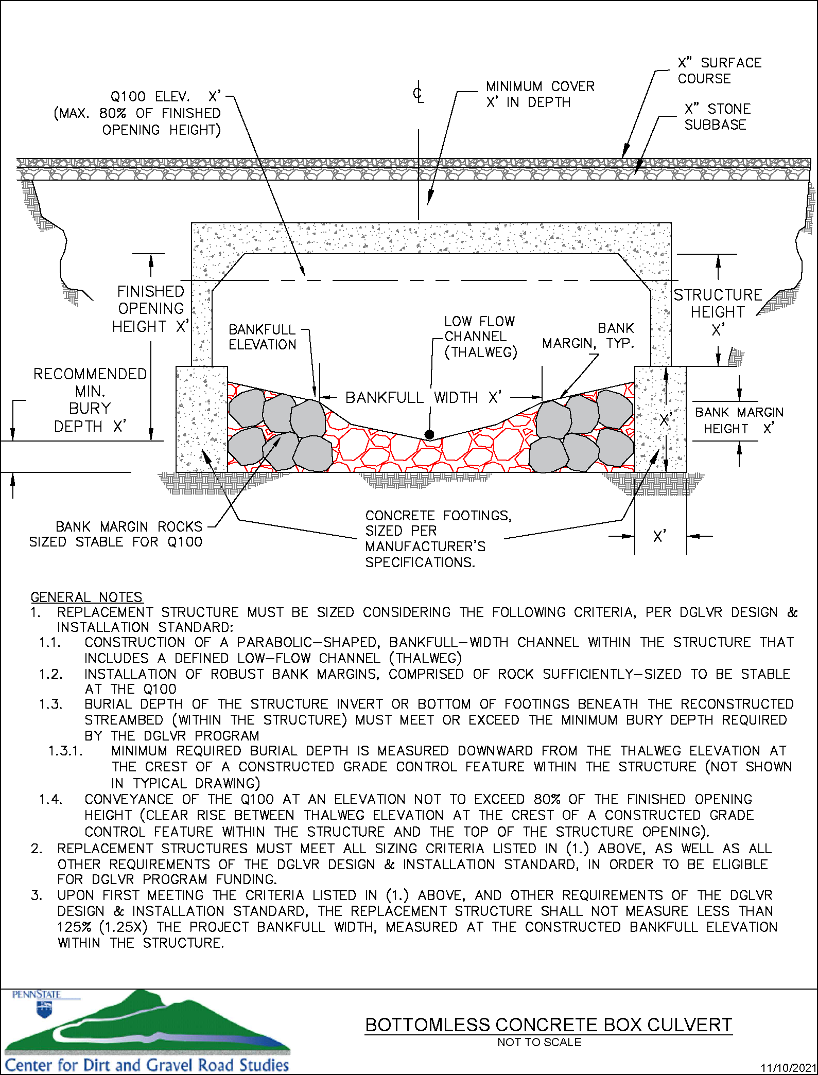
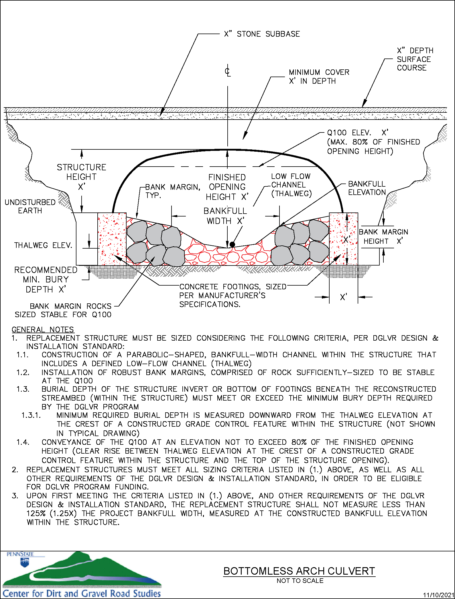
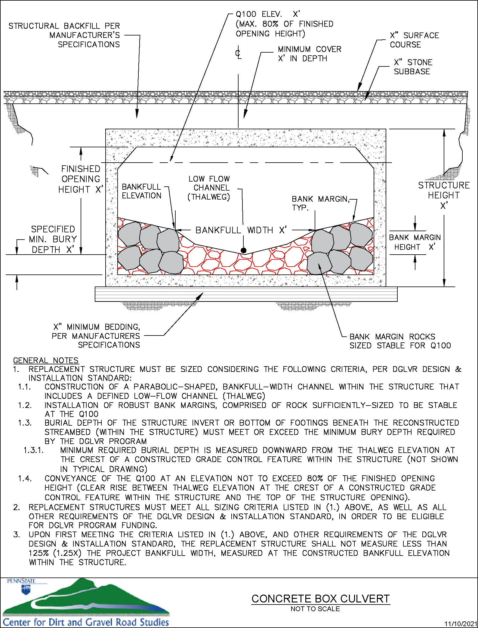
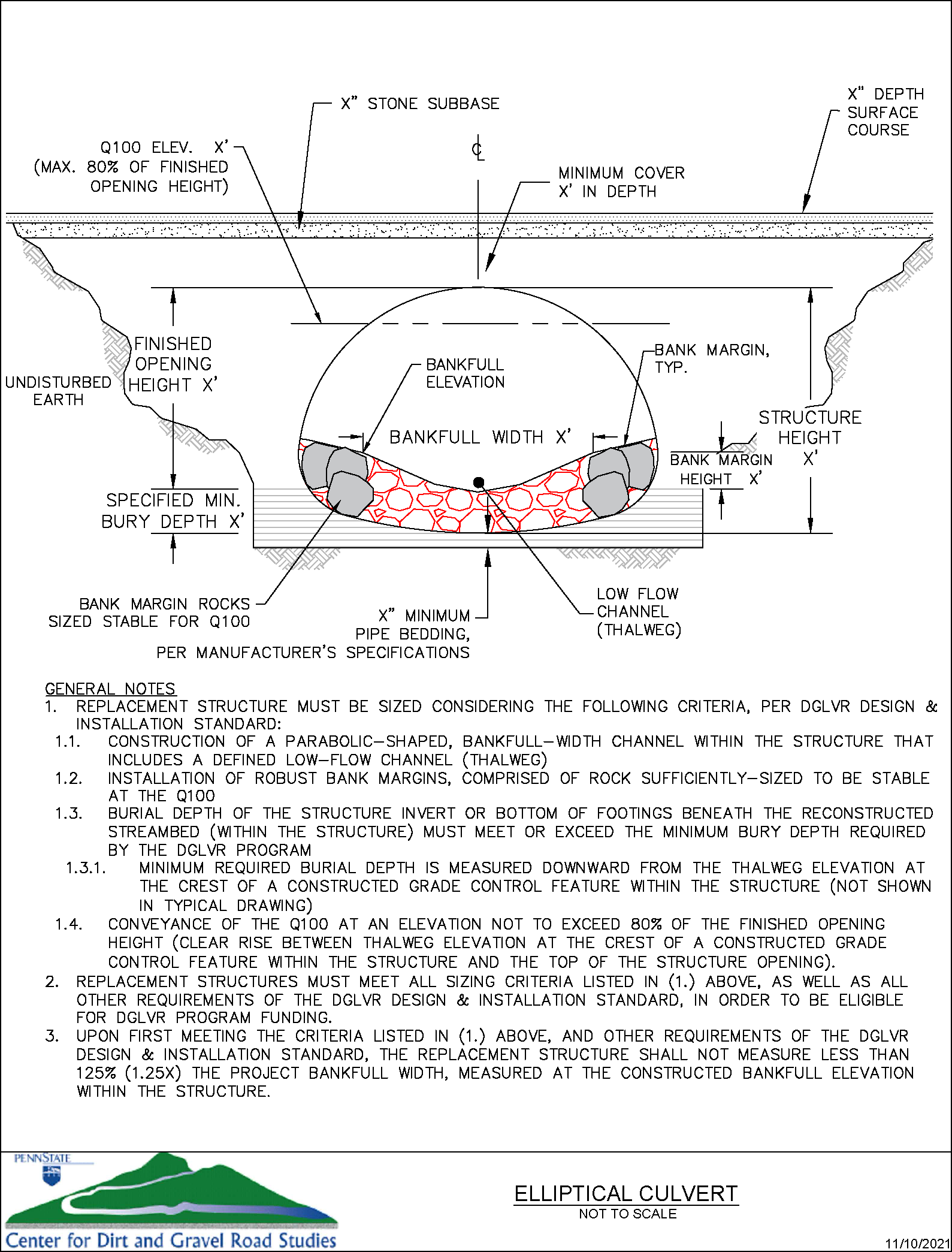
D. New stream crossing structures shall be designed to pass, at a minimum, the 100-year discharge (Q100) at a water surface elevation not to exceed 80% of the finished opening height.
A Hydrologic and Hydraulic (H&H) Study is required that includes:
1. finished thalweg elevations, and
2. clearly labeled discharge values and water surface elevations at the proposed crossing inlet for Q2, Q10, Q25, Q50, and Q100.
E. Grade controls, bank margins, and key pieces shall, at a minimum, be designed to be stable at Q100.
F. Structures must be of adequate width to accommodate the bankfull width of the stream at the final bankfull elevation with stable bank margins. Once these design criteria are met, the structure width shall not be less than 1.25x the bankfull width of the stream at the bankfull elevation.
G. In project design and construction, bankfull channel dimensions must be based upon project site-specific field measurements. Channel dimensions derived from other methods, such as modeling of estimated bankfull discharge, shall not be utilized.
H. New structures must be properly aligned with the channel, unless not feasible due to permitting restrictions or other constructability restraints. See Attachment A and the SCC GP-11 Permit Memo (Appendix E of the DGLVR Stream Crossing Replacement Technical Manual) for additional clarification of permitting, including minor channel realignments that might be authorized with a GP-11 for stream crossings designed to this Standard.
I. Consider floodplain connectivity when necessary (e.g., high water by-pass, overflow pipes, etc.). Floodplain or overflow pipes must be placed a minimum of one bankfull-width distance outside of the bankfull channel.
J. Structures must be designed and constructed to accommodate the passage of aquatic organisms through the structure.
K. Round pipes over 36” in diameter may not be utilized for stream crossings.
L. Low flow channels with well-defined bank margins must be built through the structure.
M. Site Assessment:
1. A longitudinal profile survey is required for each site prior to project design and/or permitting. The surveyed stream segments must extend far enough to capture existing channel slopes upstream and downstream of the crossing and must include an appropriate reference reach to support project design. To determine applicability, the reference reach slope must be +/- 25% of the proposed continuity slope of the reconstructed streambed, unless otherwise approved by the SCC. If an appropriate reference reach is not located near the crossing, a separate survey may be conducted on an appropriate reference reach further upstream or downstream of the crossing. The reference reach must begin and end at existing grade control features and must, at minimum, include two consecutive sequences of repeating bed features (eg., riffle/pool/riffle/pool/riffle). A longer reference reach, including additional bedform sequences, is encouraged in order to provide more reliable design criteria.
i. The longitudinal profile survey must extend both upstream and downstream of the crossing and include data points associated with the existing structure and roadway surface.
ii. A sufficient number and locations of data points must be collected to determine the stream channel features that are critical to a successful structure replacement. These include:
1. channel and structure slope,
2. grade control types, lengths, and spacing,
3. pool scour depth,
4. potential tie-in points,
5. aggradation wedges,
6. plunge pools,
7. vertical offset of the streambed adjacent to the structure, and
8. available roadway cover.
iii. The longitudinal profile survey must extend a minimum of 150’ upstream and 150’ downstream of the existing crossing. Additional length of survey may be necessary to capture a suitable reference reach to support the project design. Actual length of the longitudinal profile survey is dependent upon the site conditions, availability of a suitable reference reach, channel size, and distance necessary to accurately capture existing channel slopes both upstream and downstream of the crossing. The longitudinal profile survey must extend from an existing grade control upstream of the crossing feature to an existing grade control feature downstream of the crossing.
2. Cross-section surveys are required at a minimum of two locations. At minimum, surveys must be completed at a grade control crest within the reference reach and at the deepest point in the outlet scour pool (if present). If no outlet scour pool exists, this survey should capture the maximum depth of a pool feature from the reference reach. At minimum, each surveyed cross section must include data points on both streambanks capturing top-of- bank, bankfull, and right/left edge of water. Instream data points must include a minimum of three streambed points, including the thalweg (low-flow channel).
3. Refer to the DGLVR Stream Crossing Replacement Technical Manual for more guidance on Site Assessment requirements.
N. The engineer is responsible for the Site Assessment data they use. If conservation districts provide Site Assessment data, the engineer has discretion to use the provided data or conduct their own surveys. If a Site Assessment is completed by the design engineer to support their project design, the conservation district technician is required to be on-site while the surveys are being performed by the engineer and/or surveyor. The engineer shall provide the completed survey and Site Assessment data to the conservation district technician. The Site Assessment data provided to the conservation district shall include stationing, elevations, and notations of key stream features as outlined in (M.) above.
O. The Site Assessment data (from longitudinal profile and cross section surveys) described above shall be used to inform project design considerations, including the following:
1. Minimum stream substrate depth (measured below the low flow channel at a grade control crest, to the structure invert or bottom of the footings) is to be based on the maximum pool depth in the reference reach with a minimum safety factor multiplier as listed in Table 1. Alternatively, minimum bury depth can be determined using industry-accepted scour analysis and modeling tools for stream system analysis and/or bridges (storm sewer models are not acceptable for stream crossing scour analysis).
| Continuity Slope | Pool Depth Multiplier |
| 0% – 2.0% | 1.5 |
| 2.1% – 4.0% | 2.0 |
| > 4.0%* | 2.5 |
* Structures installed on reconstructed reach stream slopes >4.0% must be bottomless. The 2.5 safety factor multiplier is to establish the recommended minimum bottom of footing buried depth. The final footing buried depth is to be determined by the Engineer in the project design.
2. Minimum substrate depth (measured below the low flow channel at a grade control crest, to the structure invert or bottom of the footings) shall be 24 inches, or the depth determined with scour analysis models or the Anticipated Scour Depth, whichever is greater.
3. The design shall identify stable tie-in points at grade control features (either existing or to be constructed). The distance between the upstream and downstream tie-in points must extend far enough in both directions to restore channel continuity upstream, through, and downstream of the structure.
4. In-stream channel grade control(s) are required for re-constructing the stream channel and/or stabilizing the stream bed and channel through the reconstructed stream reach. Types of grade control features utilized must be the same type as those within the appropriate reference reach. Design of grade control feature length and spacing shall be based upon the Site Assessment data.
5. Design of the cross-sectional shape of the reconstructed reach must be based on Site Assessment data.
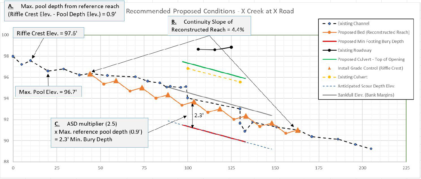
Figure 1. Determining Minimum Bury Depth through the Anticipated Scour Depth / Pool Depth Multiplier Method. A. Maximum reference reach pool depth is defined as the greatest vertical difference between each pool bottom elevation and the elevation of the corresponding grade control crest immediately upstream (in this example, 0.9’). B. The slope of the stream segment to be reconstructed in order to reestablish channel continuity upstream, through, and downstream of the replacement crossing (“continuity slope”) determines the multiplier value to be applied. In this example, a continuity slope of 4.4% corresponds to a pool depth multiplier value of 2.5 (see Table 1, above). C. Minimum bury depth is the product of the maximum reference pool depth x pool depth multiplier. In this example, 0.9’ x 2.5 = 2.3’ minimum bury depth. The minimum bury depth defines the minimum depth to which the bottom of footings (or structure invert) must be installed. This depth is measured downward from the thalweg elevation at the crest of a constructed grade control feature within the replacement structure.
P. Stream crossing projects will likely require work outside of the right-of-way to reconstruct the stream channel, install grade controls, and/or allow for construction access to the stream and structure. Before working outside the right-of-way, the grant recipient must obtain written permission from the landowner(s). In instances where written off right-of-way permission cannot be obtained to do work necessary to achieve channel continuity, the project cannot be completed with DGLVR funds.
Q. The grant recipient or engineer must provide all plans and specifications to the conservation district. The conservation district must review the documents and provide written confirmation to the grant recipient or engineer that those plans and specifications comply with DGLVR policy and the Stream Crossing Standard before they are submitted (or resubmitted) for permit review.
R. Side Slopes: Make all finished cut and fill road slopes stable for the materials involved. Make the side slopes in soil materials no steeper than 2 horizontal to 1 vertical (2:1) in cut slopes or 3 horizontal to 1 vertical (3:1) for fill slopes. Make rock cuts or fills no steeper than 2 horizontal to 1 vertical (2:1).
S. All stream crossing replacement structures must include a headwall and an endwall.
T. Quarried aggregate rip-rap for use as grade control, bank margins, or bank stabilization: Use only rock that is sound, durable, and able to withstand exposure to air, water, and freezing and thawing. Aggregate must be obtained from a Pennsylvania Department of Transportation approved source, or must be tested and meet the following criteria:
1. Abrasion Resistance: The loss of mass (LA Abrasion) shall be less than 45%: Determine the resistance to abrasion using the Los Angeles Abrasion test, ASTM C131.
2. Soundness: Determine the percentage of mass (weight) loss of each fraction of the coarse aggregate after five cycles of immersion and drying using a sodium sulfate solution according to PTM No. 510. The maximum weighted percent loss allowed is 20%.
U. Vegetation: Revegetate and permanently stabilize all disturbed areas as soon as practical after construction activities are complete. Revegetation and site stabilization shall comply with the PA Chapter 102 Erosion Control requirements (see the PA Erosion and Sediment Pollution Control Program Manual for additional guidance).
V. Road Approaches to Stream Crossings: Ensure that the roadway approaches are stable and road drainage systems have been addressed and are adequate to divert road drainage (e.g., ditches, turnouts, etc.) away from the stream and structure in a manner that prevents erosion.
W. Project work cannot start until all federal, state, and local permits are obtained, if needed. In particular, any required DEP 102/105 permits must be obtained before construction may begin. See the SCC GP-11 Permit Memo (Appendix E of the DGLVR Stream Crossing Replacement Technical Manual) for additional clarification.
V. STRUCTURE SELECTION
A. Bottomless structures shall be used for all structure replacements where the continuity slope of the channel to be reconstructed through the project area will be greater than 4.0% or the bankfull width is over 20’, as determined by the longitudinal survey.
B. Structures with inverts/bottoms may be used for structure replacements where the continuity slope of the channel to be reconstructed will be 4.0% or less (as determined by the longitudinal survey) or on sites over 4.0% where it is determined by a geotechnical investigation report that soil bearing pressure cannot support structure abutments or footings.
VI. CONSTRUCTION PLANS AND SPECIFICATIONS
A. The grant recipient must provide all permit applications, Site Assessment data, design plans and specifications (per the DGLVR Stream Crossing Design and Installation Standard) to the conservation district for review. The conservation district must review the documents and provide written confirmation to the grant recipient that these submitted documents comply with DGLVR policy and the Stream Crossing Standard before they are submitted (or resubmitted) for permit review.
B. Construction plans and specifications shall be designed and prepared in accordance with this Stream Crossing Standard. Construction plans and specifications shall be prepared for all stream crossing projects, regardless of who the contractor or installer may be (applies to projects installed by the grant recipient, such as a municipality). Clearly describe the requirements for applying the practice to achieve its intended purpose in the plan and specifications. At a minimum, the plan and specifications must include the following:
1. Existing conditions of the project site, including but not limited to the full longitudinal profile survey and cross sections of the stream, existing stream crossing, stream crossing and channel slope, road approaches, and delineated wetlands (if applicable).
2. Geographic location and bankfull width of stream.
3. Proposed stream crossing structure width, length, and height with profile and typical cross sections.
4. Elevations and locations of abutments, footings, wingwalls, and other associated appurtenances.
5. Details for stream bed reconstruction (e.g., channel width, proposed channel alignment, channel side slopes, stream bed slope, and location of tie-in points). See Attachment A and the SCC GP-11 Permit Memo (Appendix E of the DGLVR Stream Crossing Replacement Technical Manual) for additional clarification of permitting, including minor channel realignments that might be authorized with a GP-11 for stream crossings designed to this Standard.
6. Location and details for low flow channel width, depth, and material size and types.
7. Locations and construction details, including rock sizing, in-stream structures, grade controls, and/or bank stabilization structures (if applicable).\
8. Depth, gradation, and composition of material for streambed restoration. Refer to the DGLVR Stream Crossing Replacement Technical Manual for more guidance on determining substrate gradation and composition.
9. Specification for compaction of placed streambed material.
10. Details for scour hole restoration and reestablishing channel cross section.
11. Structure manufacturer’s details, specifications, and installation instructions.
12. Thickness, compressive strength, reinforcement, testing, and other special requirements for concrete according to the manufacturer specifications, if applicable.
13. Load limits for bridges and/or culverts, including signage and guide rail per state or local codes.
14. Location of all utilities and notification requirements (PA One Call).
15. Location and elevation of survey benchmarks.
16. Method of surface water diversion and dewatering during construction.
17. Erosion and Sedimentation Control Plan, if applicable.
18. Vegetative requirements that include seed and plant materials to be used, establishment rates, and season of planting.
19. Cross section view of the proposed structure that clearly notes proposed streambed thalweg elevation (at the crest of a constructed grade control feature), Q100 water surface elevation, and top of structure opening elevation.
20. Additional site-specific requirements.
VII. CONSTRUCTION
A. The grant recipient or engineer must provide all draft bid packages (if applicable) to the conservation district. The conservation district must review the draft bid documents and provide written confirmation to the grant recipient or engineer that those draft bid documents comply with DGLVR policy and the Stream Crossing Design and Installation Standard before they are provided to potential bidders. All bid documents and practices must conform with municipal codes and other standard procurement requirements of the grant recipient.
B. Final construction documents shall include, at a minimum, the following items:
1. Bidding Documents (if applicable).
2. Construction Plan.
3. Erosion and Sedimentation Control Plan.
4. Construction Specifications.
C. At a minimum, two benchmarks must be set by the engineer or surveyor in an area outside of the zone of construction and disturbance.
D. Critical Stages of Construction to be inspected by the engineer (and/or engineer’s designee) at the time of installation is required. Critical Stages include, but are not limited to, the following:
1. Installation of structure subgrade and bedding materials and establishing inverts/elevations.
2. Installation of footings, abutments and structure appurtenances.
3. Installation of grade control features, bank margins, and streambed substrate.
4. Installation or placement of stream crossing structure.
5. Compaction and backfill of stream crossing structure.
E. Conservation districts must be on-site regularly during construction to ensure that the DGLVR Program Policy and Stream Crossing Standard are being met. Conservation districts must be onsite during installation of the Critical Stages of Construction defined in VII. D, above.
F. Certification and Documentation of Critical Stages of Construction: The engineer shall provide the project owner a signed and sealed certification form (Attachment B) indicating that the critical stages of construction outlined in Section VII.D were inspected and installed in accordance with the construction documents and DGLVR Stream Crossing Standard. The engineer must also provide the project owner with red-lined construction documents that indicate any changes in the as-built conditions of the project compared to the design plans.
References
1. Dirt, Gravel, and Low Volume Road Maintenance Program Administrative Manual. May 2022.
2. Dirt, Gravel, and Low Volume Road Stream Crossing Technical Manual. May 2022.
3. U.S.D.A. Forest Service Stream Simulation Manual: An Ecological Approach to Providing Passage for Aquatic Organisms at Road-Stream Crossings. May 2008.
4. Pennsylvania Department of Environmental Protection Erosion and Sediment Pollution Control Program Manual. Technical Guidance Number 363-2134-008. March 2012.
Attachments
Attachment A: Chapter 105 General Permit Types Most Applicable to Stream Crossing Replacements

Attachment B: Inspection and Documentation of Critical Stages of Construction Certification Form

Attachment C: Typical Detail Drawings
Click the left/right arrows to scroll through the detail drawings.